PCB Design Verification for an Automotive Radar Sensor System
Analysis, modeling, layout improvements
The client was working on a radar sensor system for self-driving vehicles. It would measure the distance to nearby objects like cars, obstacles, and pedestrians. The solution was to form part of the Advanced Driver Assistance System (ADAS) functionality of autonomous cars.
Solution
Direct Current (DC) Simulation
The initial shape of the PCB copper area was insufficient to deliver current to the electronic components. Most likely, it would cause overheating and voltage drops in the power delivery network (PDN) affecting the reliability of the device.
We proposed to increase the size of the copper area and eliminate bottlenecks along with right angles. This would reduce excessive current density and help avoid overheating.

Alternating Current (AC) Simulation
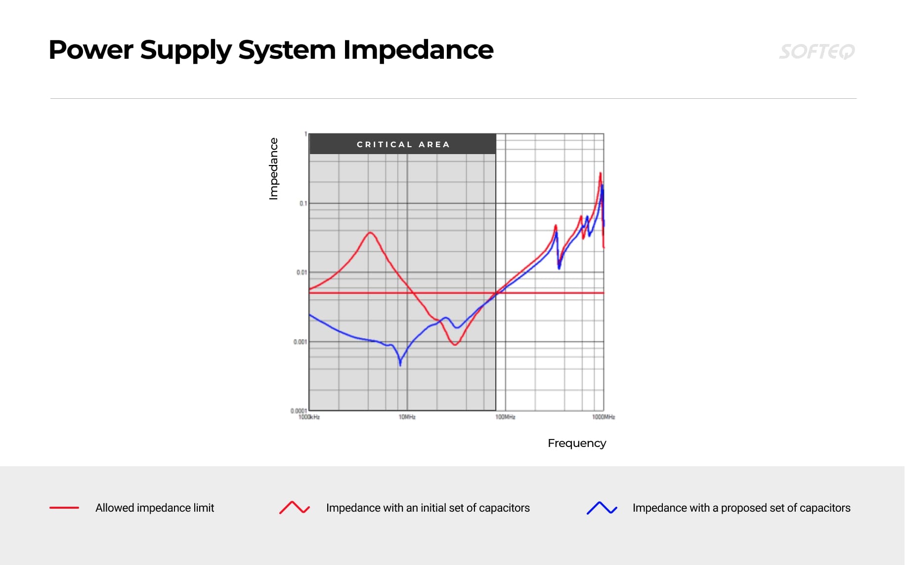
The customer’s device will operate at high frequencies. This will also increase the impedance of the entire power system. Excessive impedance in a high-frequency range can generate excessive voltage noise, ground bounce, and switching errors on chips, all of which can cause the device to malfunction. Special capacitors are used to solve this problem.
In order to check if the capacitors were selected correctly in the original design (dimensions, capacity, number), we performed an AC decoupling simulation. The results showed that with the initial set of capacitors the power supply system significantly exceeded the permissible impedance limit. We proposed another set of capacitors with higher capacitance values, which significantly improved the impedance.
Checking the Signal Integrity for High-Speed Interfaces
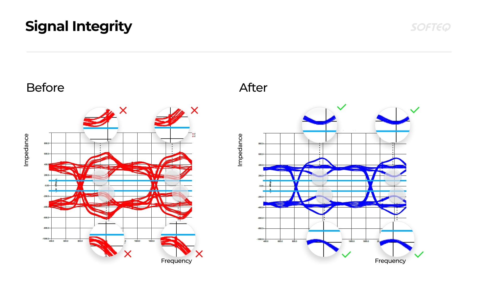
As the customer’s device supports high-speed interfaces (memory, Ethernet, ADCs), it’s sensitive to any delay in signal transmission between chips. Physical properties of the board materials—copper, dielectric, fiberglass—can affect the transmission speed and cause read errors. We conducted signal integrity (SI) analysis to ensure that fast signals will not be severely distorted while transmitting from driver to receiver and will match voltage thresholds and timing requirements.
The simulation showed that the initial signal shape was too close to the permitted voltage thresholds. This might cause data degradation and trigger false responses. We suggested including additional resistors in the design. This would increase the gap between the signal curve and the allowed threshold while reducing jitter and inter-symbol interference (ISI).
The simulation showed that the initial signal shape was too close to the permitted voltage thresholds. This might cause data degradation and trigger false responses. We suggested including additional resistors in the design. This would increase the gap between the signal curve and the allowed threshold while reducing jitter and inter-symbol interference (ISI).
We also verified the memory layout and suggested some changes according to the general DDR routing rules in order to avoid potential errors during read/write operations.
Thermal Analysis
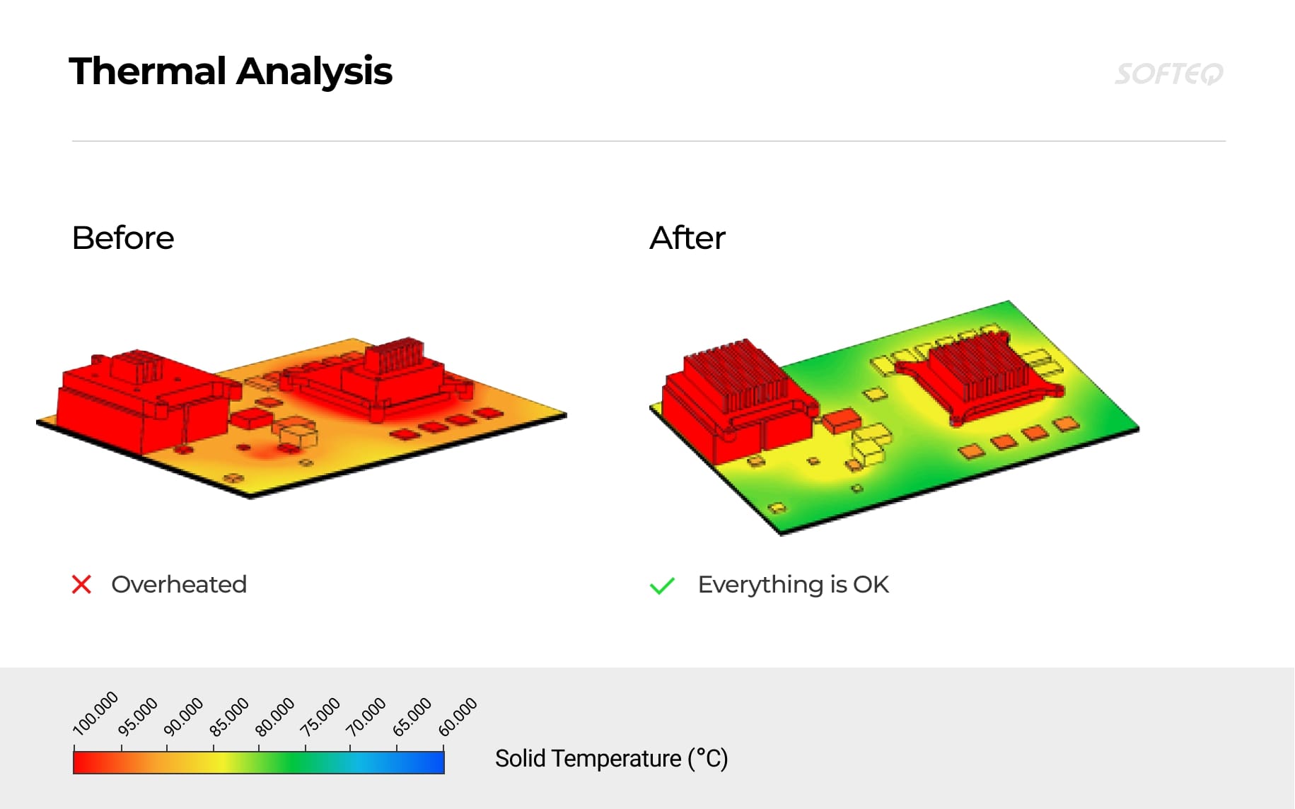
Chips on the board operate at high speeds and with large volumes of information. This requires a large amount of energy, resulting in heat dissipation. Chip overheating reduces the speed of its operation and in some cases causes whole system shutdowns. The team conducted a thermal analysis to check the initial configuration of cooling radiators that dissipate heat into the environment and reduce the chip’s temperature.
The simulation showed significant overheating of the main components and the whole board. For most chips, the maximum temperature exceeded working limits. We suggested changing the heatsink configuration to ensure better heat dissipation from the sources.
Need Expert Help with Custom PCB Design?
We know how to fast-track your product development from PCB design to board bring-up while shortening the production cycle Learn how